Simple Centrifuge
Clean waste vegetable oil (WVO), bio diesel, lube oils, and even hydraulic oil in your garage
Main
Ordering
History
FAQ
Contact
Lab Centrifuge
Gallery
Videos
About
 
Photo Gallery - This gallery represents the work over several years. Some designs have been replaced and/or updated as time progressed. Most images contain a date stamp visable on the large version. Please note the date when viewing. We are always experimenting with new concepts and designs. If you have any questions about any photo please contact us.
Total photos in gallery 1296 - Latest photo update 2021/12/10 18:48:01
Asterisk(*) indicates new photos in the past 30 days
Adapter 56C to 56J ( 15 )
Algae Recovery ( 42 )
Bacterial fermentation ( 1 )
Balancer Mandrels ( 8 )
Bearing replacement ( 25 )
Botry Culture ( 2 )
Building a gantry ( 16 )
Chestnut Extract ( 9 )
CNC Coolant ( 6 )
Coconut Oil ( 8 )
Construction ( 43 )
Contaminated diesel ( 2 )
Craig's Machine ( 31 )
Cross Drill End Bell ( 10 )
Crude oil ( 5 )
Custom motor shaft ( 23 )
Experimental Motor ( 19 )
Explosion proof motor ( 3 )
Feed Cone ( 29 )
Feed Cone with Fins ( 8 )
Feed Tube ( 3 )
Filter Paper ( 7 )
Ford on WMO ( 2 )
Foundry ( 5 )
Foundry 2 ( 18 )
Gear pump ( 2 )
Grinding fluid ( 19 )
Grinding fluid 2 ( 14 )
Heaters ( 9 )
History ( 11 )
Homemade Diesel ( 7 )
Homemade diesel 2 ( 41 )
Homemade Diesel 3 ( 15 )
Homemade Diesel 4 ( 12 )
How it works ( 3 )
Hydraulic Oil ( 3 )
Keyless Bushing ( 11 )
Lab Centrifuge ( 16 )
Lab Centrifuge 2 ( 18 )
Lapidary Cutting Oil ( 2 )
Lock motor shaft ( 6 )
Magnesol removal ( 6 )
Microwave heater ( 7 )
Misc. Mods ( 4 )
Mitsubishi 4x4 on WMO ( 10 )
New Feed Cone ( 16 )
New Feed Tube ( 7 )
New Rotor 2013 ( 24 )
New rotor design ( 16 )
Oil and Contaminants ( 47 )
Oil Skimmer ( 8 )
Our Shop ( 37 )
Peristaltic Pump ( 32 )
Powder Coating ( 10 )
Renderings ( 8 )
Retrofit rotor for WVOD ( 17 )
Rework Mount ( 10 )
Rotor fins ( 34 )
Rotor Fins One Piece ( 6 )
Seal ( 6 )
Sea Weed ( 4 )
Sediment removal ( 16 )
See thru lid - Building ( 16 )
See thru lid - Testing ( 28 )
Sight Glass ( 6 )
Skim Tube ( 56 )
Skim Tube for VCO ( 8 )
Small Settling Tank ( 14 )
Tanks ( 9 )
Tanks - Complete System ( 13 )
Tap drain ( 10 )
Testing Seal Screws ( 6 )
Tests by fuelfarmer ( 22 )
Turn key machine ( 38 )
Two part rotor ( 30 )
Ultrasonic filter cleaning ( 8 )
Updates ( 26 )
Users Machines ( 34 )
Vacuum pickup ( 3 )
VW on WMO ( 7 )
Water-Oil Seperator ( 7 )
Water trap ( 5 )
Wine Clarification ( 4 )
WVO Heat Tests ( 7 )
WVO Pump ( 6 )
WVO Tests ( 14 )
Experimental Motor
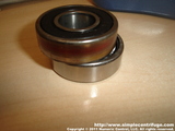
I have been thinking about motors for a while. After rebuilding a few over the past few days I have some new insight and a few ideas. I decided to build a proto-type motor of my own design. The motors normally use 6203 ball bearings. The top bearing is locked. The bottom bearing is preloaded with a wave spring. This works great in the horizontal position but is less than ideal in the vertical position, especially during start and shutdown. As the rotor has increased in capacity so has the demands on the bearing assembly. This is a quick proof of concept solution. The upper bearing is being replaced with a double row angular contact bearing. This will handle both radial and axial forces. The bottom bearing will still be a floating ball bearing.
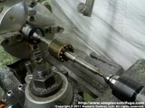
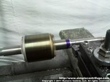
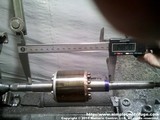
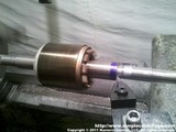
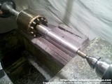
I mounted the stock rotor between centers. The new bearing is 5mm taller (thicker) than the original so I have to remove some material. I marked the basic layout with some blue layout fluid. Checking the cut.
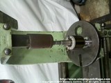
The bottom of the shaft has to have clearance for the bearing to seat fully. This is done easily. After chamfering and a quick cleanup with an abrasive pad. Pressed the new bearing on with the arbor press. Photo is sideways.
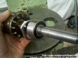
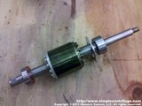
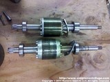
This is the new bearing installed. Notice how much larger the new bearing is. Here is another photo. This is the modified rotor along side the original.
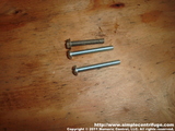
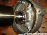
Notice how much taller the new bearing is. Had to replace the original 10-32 screws with some longer ones. This is the upper bearing locked into place.
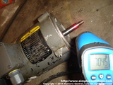
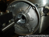
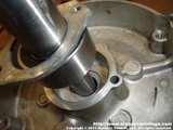
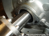
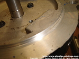
Re-assembled the motor and did a little beyond specification testing. Here the motor is just above 7000 rpm. The bearing on top came out of a motor that had run at 7200 rpm for a year. It appears the bearing spun in the housing, likely once it heated up the aluminum housing. The bearing still feels good. I decided boring the end bell would be easier than turning the shaft. Here I'm boring the end bell an additional 5.5 mm to accommodate the larger double row bearing.
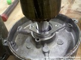
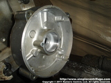
The end bell has a steel sleeve which is sized for a 12 mm thick bearing. You can see the transition from steel to aluminum. Installing the bearing into the end bell. Bearing installed. Note that I was able to use the stock bolts.
This end bell is also cross drilled with a vertical weep hole. I modified this end bell a few years ago and it just happened to be the one I decided to modify for the angular contact bearing.    
Numeric Control, LLC
PO Box 916
Morton, WA 98356