Simple Centrifuge
Clean waste vegetable oil (WVO), bio diesel, lube oils, and even hydraulic oil in your garage
Main
Ordering
History
FAQ
Contact
Lab Centrifuge
Gallery
Videos
About
 
Photo Gallery - This gallery represents the work over several years. Some designs have been replaced and/or updated as time progressed. Most images contain a date stamp visable on the large version. Please note the date when viewing. We are always experimenting with new concepts and designs. If you have any questions about any photo please contact us.
Total photos in gallery 1296 - Latest photo update 2021/12/10 18:48:01
Asterisk(*) indicates new photos in the past 30 days
Adapter 56C to 56J ( 15 )
Algae Recovery ( 42 )
Bacterial fermentation ( 1 )
Balancer Mandrels ( 8 )
Bearing replacement ( 25 )
Botry Culture ( 2 )
Building a gantry ( 16 )
Chestnut Extract ( 9 )
CNC Coolant ( 6 )
Coconut Oil ( 8 )
Construction ( 43 )
Contaminated diesel ( 2 )
Craig's Machine ( 31 )
Cross Drill End Bell ( 10 )
Crude oil ( 5 )
Custom motor shaft ( 23 )
Experimental Motor ( 19 )
Explosion proof motor ( 3 )
Feed Cone ( 29 )
Feed Cone with Fins ( 8 )
Feed Tube ( 3 )
Filter Paper ( 7 )
Ford on WMO ( 2 )
Foundry ( 5 )
Foundry 2 ( 18 )
Gear pump ( 2 )
Grinding fluid ( 19 )
Grinding fluid 2 ( 14 )
Heaters ( 9 )
History ( 11 )
Homemade Diesel ( 7 )
Homemade diesel 2 ( 41 )
Homemade Diesel 3 ( 15 )
Homemade Diesel 4 ( 12 )
How it works ( 3 )
Hydraulic Oil ( 3 )
Keyless Bushing ( 11 )
Lab Centrifuge ( 16 )
Lab Centrifuge 2 ( 18 )
Lapidary Cutting Oil ( 2 )
Lock motor shaft ( 6 )
Magnesol removal ( 6 )
Microwave heater ( 7 )
Misc. Mods ( 4 )
Mitsubishi 4x4 on WMO ( 10 )
New Feed Cone ( 16 )
New Feed Tube ( 7 )
New Rotor 2013 ( 24 )
New rotor design ( 16 )
Oil and Contaminants ( 47 )
Oil Skimmer ( 8 )
Our Shop ( 37 )
Peristaltic Pump ( 32 )
Powder Coating ( 10 )
Renderings ( 8 )
Retrofit rotor for WVOD ( 17 )
Rework Mount ( 10 )
Rotor fins ( 34 )
Rotor Fins One Piece ( 6 )
Seal ( 6 )
Sea Weed ( 4 )
Sediment removal ( 16 )
See thru lid - Building ( 16 )
See thru lid - Testing ( 28 )
Sight Glass ( 6 )
Skim Tube ( 56 )
Skim Tube for VCO ( 8 )
Small Settling Tank ( 14 )
Tanks ( 9 )
Tanks - Complete System ( 13 )
Tap drain ( 10 )
Testing Seal Screws ( 6 )
Tests by fuelfarmer ( 22 )
Turn key machine ( 38 )
Two part rotor ( 30 )
Ultrasonic filter cleaning ( 8 )
Updates ( 26 )
Users Machines ( 34 )
Vacuum pickup ( 3 )
VW on WMO ( 7 )
Water-Oil Seperator ( 7 )
Water trap ( 5 )
Wine Clarification ( 4 )
WVO Heat Tests ( 7 )
WVO Pump ( 6 )
WVO Tests ( 14 )
Construction
Several people have emailed to inquire as to the construction of the simple centrifuge. While the assembly is simple we decided to post a photo guide. More to come soon. You may also like to view the users gallery for additional ideas.
Start by drilling your motor mount and cutting the motor relief. The motor we supply uses a standard 56J mount. This is the mock layout. Note the well casing has been turned and chaffered. The center hub has a slight slope, this was turned from cold rolled steel. The motor shaft is wrapped with paper to center the center hub for welding.
A length of pipe is cut to hold the hub tight during welding. This is the hub tack welded in place. Next completely weld the hub in place.
The rotor is then wrapped in paper to center the splash ring during welding. The ring is then tack welded into place. Remove the part from the motor and clamp firmly to the welding table. This is critical to prevent excessive warping.
Stitch weld the ring a few inches at a time until you have completed the entire ring. Several people have had concerns about the bolts leaking. These are special self sealing stainless steel bolts. They have a built in o-ring for a tight seal. We cleaned up the edges on the mill.
Tack weld the sides in place. Weld the bottom in place. Drill holes for inner drain and main outlet.
Holes as seen from the inside. Elbow fittings welded in place. Tack weld the lid frame. This is undersized a little so the inner edge acts as a lip to help keep the clean oil inside the machine.
Weld the lid frame to the top of the machine. This is viewed from the bottom. This is the view of the lid lip from the top of the housing. Weld the legs on.
The nearly finished housing. The outer housing powder coated. This should prove to be a very durable finish. Machine with legs attached.
Wiring the motor for 110v Switch installed. Wiring diagram from motor. For 110 volts you will use the
Wiring the motor for 110v Switch installed. Wiring diagram from motor. For 110 volts you will use the "Low Voltage". The wires are numbered. Simply wire nut the correct numbers together.
This is an alternative to the expensive o-ring bolts and has the benefit of a washer to prevent loosening . They are called pressure-sealing washers and consists of a molded nitrile rubber sealing element mechanically locked into a zinc-plated steel washer. Mike decided he needed another centrifuge at the farm to process crank case oil. The next few photos detail some design changes. After the machined collar is tight then the bowl is place on the shaft. Note that the bowl is slightly higher than the top of the shaft, this allows the nut to make full contact.
Next, remove the bowl and measure the distance from the base plate to the bottom of the collar. In this case the distance is 11/16 Next we carefully cut a piece of pipe to the required height. This is a piece of 3/4 Verify everything dry fits before welding.
Next, remove the bowl and measure the distance from the base plate to the bottom of the collar. In this case the distance is 11/16". Next we carefully cut a piece of pipe to the required height. This is a piece of 3/4" pipe. Verify everything dry fits before welding.
Wrap the shaft with paper to maintain the part concentric with the shaft and tack weld. Remove the motor after tack welding part in place. Weld the splash shield into place. Next continue on and complete the rest of the housing.
Setting up the internal splash lip on the lid. This style leaks less than the angle iron style above. This is the lid with the lip welded into place. After we made this we thought we should have put a hinge on the back edge. No hinge on this one but maybe when we build another one we'll hinge it. We changed the shaft mounting to a keyless bushing. Please see this page for more details: http://www.simplecentrifuge.com/gallery-series-16.html
Wiring of Emmersion motor for 220V usage. Wiring for Baldor motor. Wiring sticker on the Baldor motor. The colored wires have numbers printed on them. Please verify the numbers when wiring. Low voltage is 120V (110V) AC and High Voltage is 240V (220V) AC.
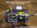
Wiring for Baldor 34-3099X998G1 motor that is typically shipped overseas for 50 Hz operation.
Hot is Blue, Nuetral is Yellow, Earth is green lug on chassis.    
Wiring for Baldor 34-3099X998G1 motor that is typically shipped overseas for 50 Hz operation. Hot is Blue, Nuetral is Yellow, Earth is green lug on chassis.    
Numeric Control, LLC
PO Box 916
Morton, WA 98356