Simple Centrifuge
Clean waste vegetable oil (WVO), bio diesel, lube oils, and even hydraulic oil in your garage
Main
Ordering
History
FAQ
Contact
Lab Centrifuge
Gallery
Videos
About
 
Photo Gallery - This gallery represents the work over several years. Some designs have been replaced and/or updated as time progressed. Most images contain a date stamp visable on the large version. Please note the date when viewing. We are always experimenting with new concepts and designs. If you have any questions about any photo please contact us.
Total photos in gallery 1296 - Latest photo update 2021/12/10 18:48:01
Asterisk(*) indicates new photos in the past 30 days
Adapter 56C to 56J ( 15 )
Algae Recovery ( 42 )
Bacterial fermentation ( 1 )
Balancer Mandrels ( 8 )
Bearing replacement ( 25 )
Botry Culture ( 2 )
Building a gantry ( 16 )
Chestnut Extract ( 9 )
CNC Coolant ( 6 )
Coconut Oil ( 8 )
Construction ( 43 )
Contaminated diesel ( 2 )
Craig's Machine ( 31 )
Cross Drill End Bell ( 10 )
Crude oil ( 5 )
Custom motor shaft ( 23 )
Experimental Motor ( 19 )
Explosion proof motor ( 3 )
Feed Cone ( 29 )
Feed Cone with Fins ( 8 )
Feed Tube ( 3 )
Filter Paper ( 7 )
Ford on WMO ( 2 )
Foundry ( 5 )
Foundry 2 ( 18 )
Gear pump ( 2 )
Grinding fluid ( 19 )
Grinding fluid 2 ( 14 )
Heaters ( 9 )
History ( 11 )
Homemade Diesel ( 7 )
Homemade diesel 2 ( 41 )
Homemade Diesel 3 ( 15 )
Homemade Diesel 4 ( 12 )
How it works ( 3 )
Hydraulic Oil ( 3 )
Keyless Bushing ( 11 )
Lab Centrifuge ( 16 )
Lab Centrifuge 2 ( 18 )
Lapidary Cutting Oil ( 2 )
Lock motor shaft ( 6 )
Magnesol removal ( 6 )
Microwave heater ( 7 )
Misc. Mods ( 4 )
Mitsubishi 4x4 on WMO ( 10 )
New Feed Cone ( 16 )
New Feed Tube ( 7 )
New Rotor 2013 ( 24 )
New rotor design ( 16 )
Oil and Contaminants ( 47 )
Oil Skimmer ( 8 )
Our Shop ( 37 )
Peristaltic Pump ( 32 )
Powder Coating ( 10 )
Renderings ( 8 )
Retrofit rotor for WVOD ( 17 )
Rework Mount ( 10 )
Rotor fins ( 34 )
Rotor Fins One Piece ( 6 )
Seal ( 6 )
Sea Weed ( 4 )
Sediment removal ( 16 )
See thru lid - Building ( 16 )
See thru lid - Testing ( 28 )
Sight Glass ( 6 )
Skim Tube ( 56 )
Skim Tube for VCO ( 8 )
Small Settling Tank ( 14 )
Tanks ( 9 )
Tanks - Complete System ( 13 )
Tap drain ( 10 )
Testing Seal Screws ( 6 )
Tests by fuelfarmer ( 22 )
Turn key machine ( 38 )
Two part rotor ( 30 )
Ultrasonic filter cleaning ( 8 )
Updates ( 26 )
Users Machines ( 34 )
Vacuum pickup ( 3 )
VW on WMO ( 7 )
Water-Oil Seperator ( 7 )
Water trap ( 5 )
Wine Clarification ( 4 )
WVO Heat Tests ( 7 )
WVO Pump ( 6 )
WVO Tests ( 14 )
Bearing replacement
Replacing the bearings in an electric motor is inexpensive and fairly easy. This shows how I do it.
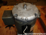
Baldor 1/3 HP motor. Start by removing the three screws from the fan shroud Remove the plastic fan. It is held on with one screw.
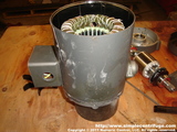
Remove the four long bolts the hold the housing together. Remove the two bearing keeper bolts from the top of the motor. Tap the top end cover loose using a soft mallet on the fan end of the shaft and the ears. You can see the cover behind the motor in this picture.
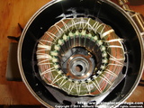
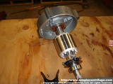
You can now lift the rotor from the motor. Using a press you can remove the upper bearing. Remove the bottom bearing in the same way.
Press on a new bottom bearing. In this case we're replacing the original shield bearings with sealed SKF bearings. Press on a new top bearing. Make sure you remember to install the bearing keeper if you removed it when flipping the part over. New bearings pressed on the rotor.
Now it's time to re-assemble the motor. First, install the bearing into the top cover and secure with the two screws. Line up the marks on the body and top cover. Tap the cover into place with the soft mallet. Install the four body bolts.
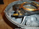
Re-install the fan and fan cover. Done. This is the capacitor start switch. It's activated during start up and the motors centrifugal force de-activates it using a spring weigh mechanism while running. Make sure this switch is clean. You should put a thin layer of grease on the spring strips. This shows the spring weight mechanism.
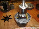
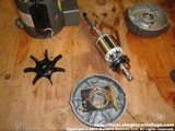
This shows most of the parts laid out after being cleaned. Notice that the new bearings have been installed. Install the bottom and orientate the weep hole. Notice how the motor is being support on a piece of pipe. You can also drill a hole in the work bench. This makes installing the shaft a lot easier. This is the top view. Make sure you remember to install the wave spring under the bottom bearing. This pre-loads the bearing and keeps everything smooth and quite.
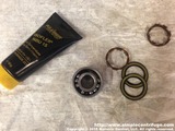
Install the shaft into the upper housing and tighten down. The upper hearing is lock in place by this plate. It's easiest to do this before dropping everything into the motor. Once you have everything lined up you can bolt it all back together. Preparing to repack a seal bearing for high speed operation. The factory grease which was barely any, was washed out with solvent after removing the seals and ball retainers. The grease being used will be Kluber Isoflex NBU-15.
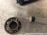
Repacking the sealed bearings with Kluber Isoflex NBU-15 grease. This is a high speed grease, typically used in machine spindles. I used a syringe from the farm store to put a little grease between each ball. Normal fill is about 20 to 30%    
Numeric Control, LLC
PO Box 916
Morton, WA 98356